When working on a complicated project like an engine swap, plenty of parts have to be custom made. The engine sitting in my BMW E30 for example was never meant to go into that body. Naturally, this means parts in the engine compartment have to be relocated, mounted differently, or new parts never meant to be in the car have to find a home.
In the past, this process involved fiddling around with metal brackets, bending, welding, drilling, and spending days on mounting a single part.
In the last couple of years though, 3D printers have made the jump from being a nerd hobby to an actually useful tool in the workshop. At the same time, 3D scanning is now an affordable technology for the home gamer.
Anyone can now make functional automotive parts using high perfomance polymers also used by OEMs.
Here is how I use these technologies exemplified by a housing/mount for the new ECU designed from scratch.
2025 I purchased a Shining3D Einstar scanner. In the past, a 3D scanner would have cost as much as a car and the available offerings were only meant for businesses and professional use. The Einstar was arguably the first scanner that was affordable, produced high quality results, but was still usable as a hobbyist.
Nowadays there are better scanners out there and the technology of the Einstar is kind of outdated, but the value for money is still hard to beat.
The benefits of 3D scanning are plentiful. I can check the fitment of parts like different radiators, air filters, etc, from the comfort of my home and without buying the physical item. With only the dimensions or a sketch of the part, I can move it around in three dimensional space and check for interference in the model of my project car. This saves both time and money and allows for much improved planning.
Where 3D scanning really shines though is the ability to print custom parts that follow the geometry of the existing car body perfectly.
The original ECU of the car was located inside of the cabin.
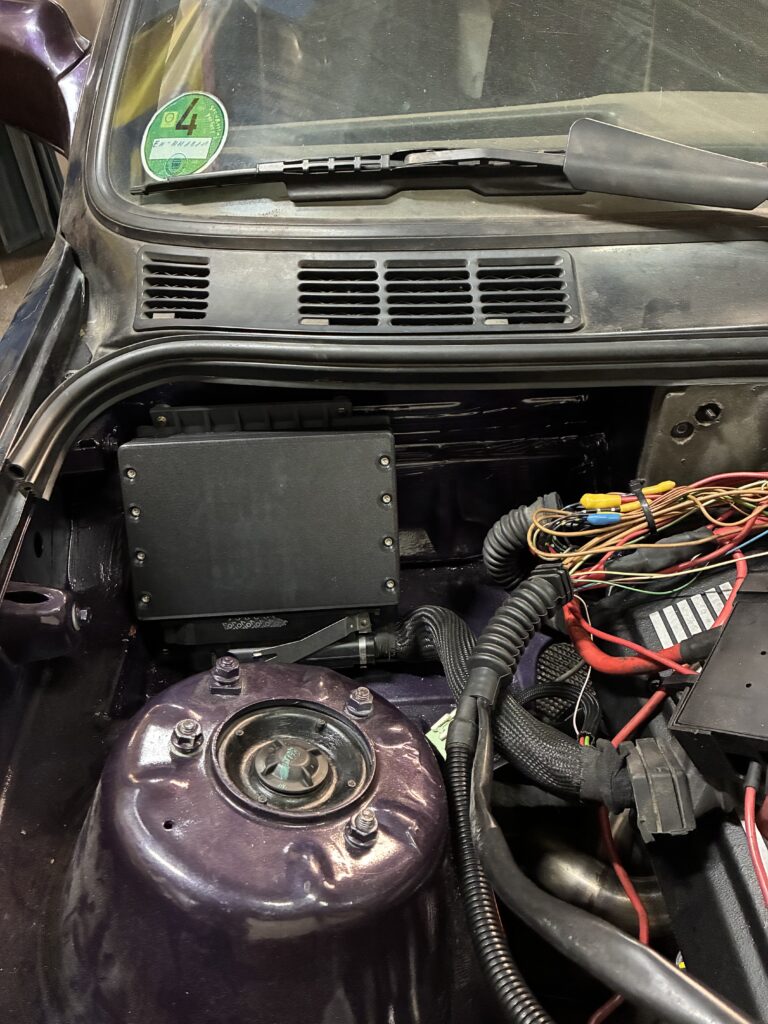
Since I relocated the battery to the boot and I had to get power to the front of the car, the hole between the engine compartment and the cabin originally used for the wiring of the ECU is now occupied by a chunky power cable instead. The space originally occupied by the battery in front was now free to use for the new ECU and other parts though.
This is the sort of rearranging I mentioned in the opening paragraph.
I took a 3D scan of the empty battery tray (and the rest of the engine compartment) before the engine was swapped into the car. There are four unused holes in the area that I could use to attach a new part with bolts.
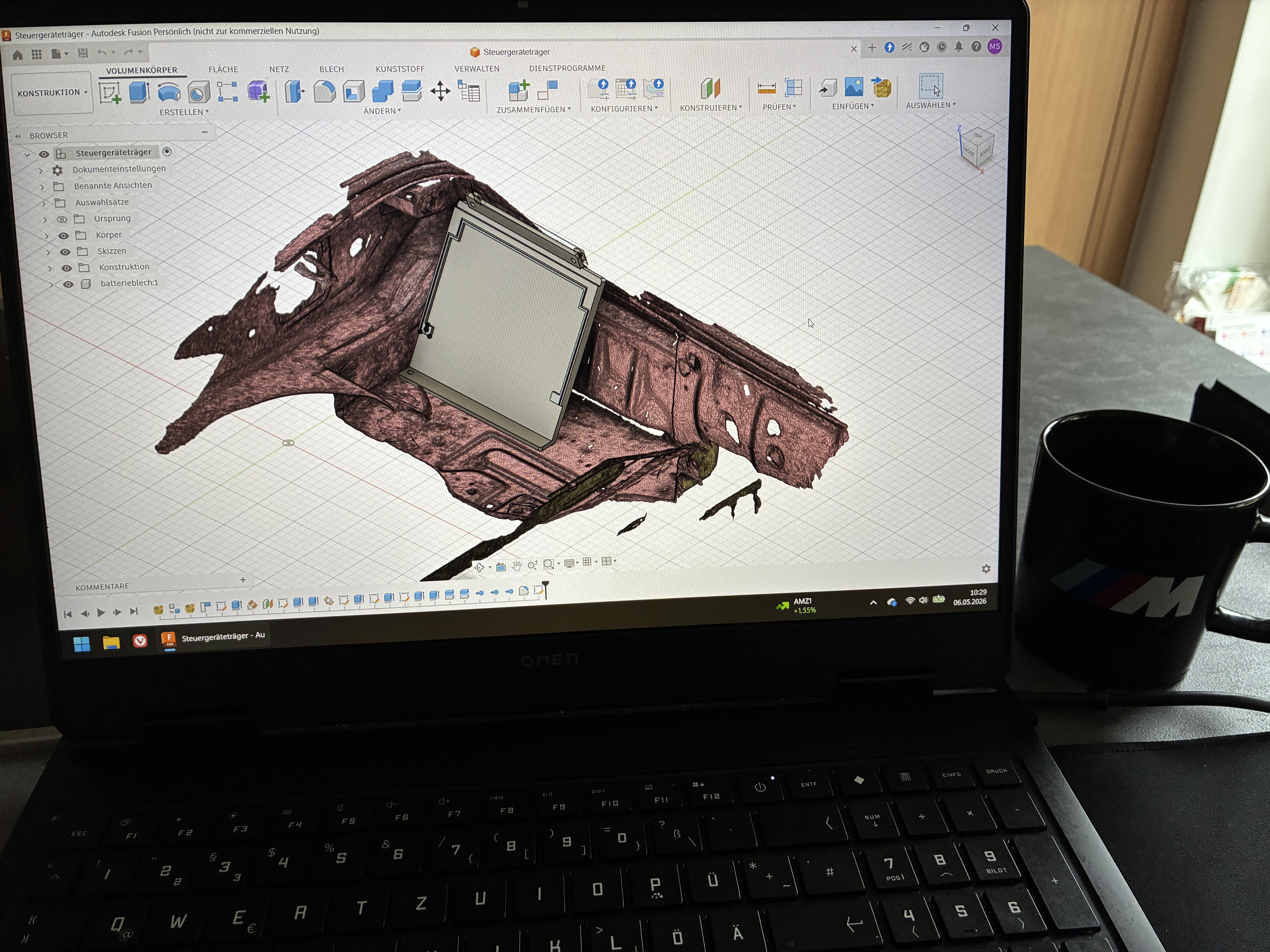
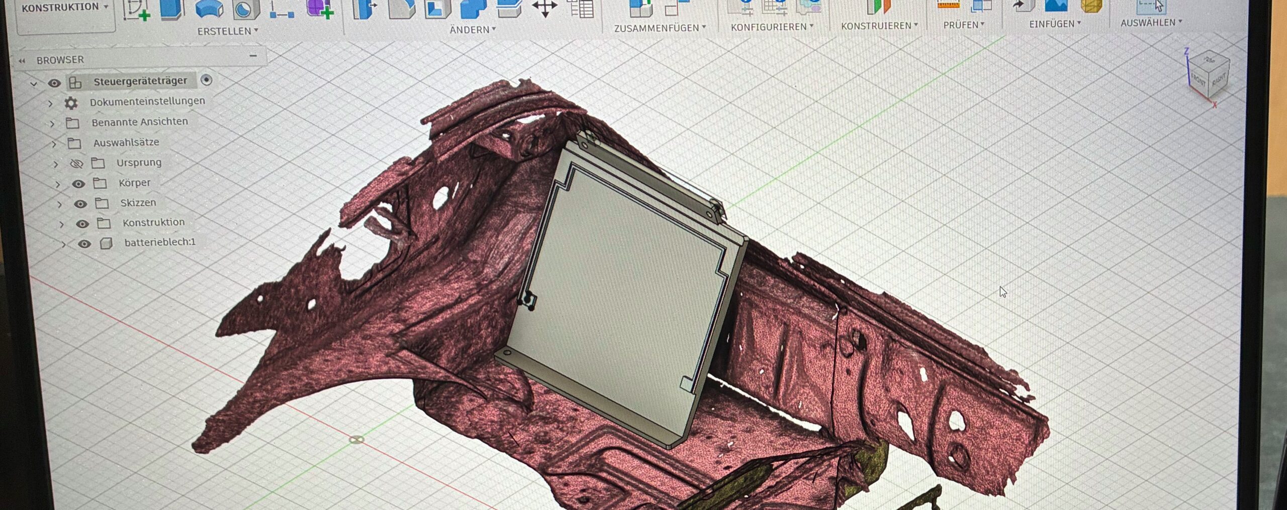
I loaded the 3D scan into my CAD software and used the reference of the geometry of the car to design a mounting plate for the ECU.
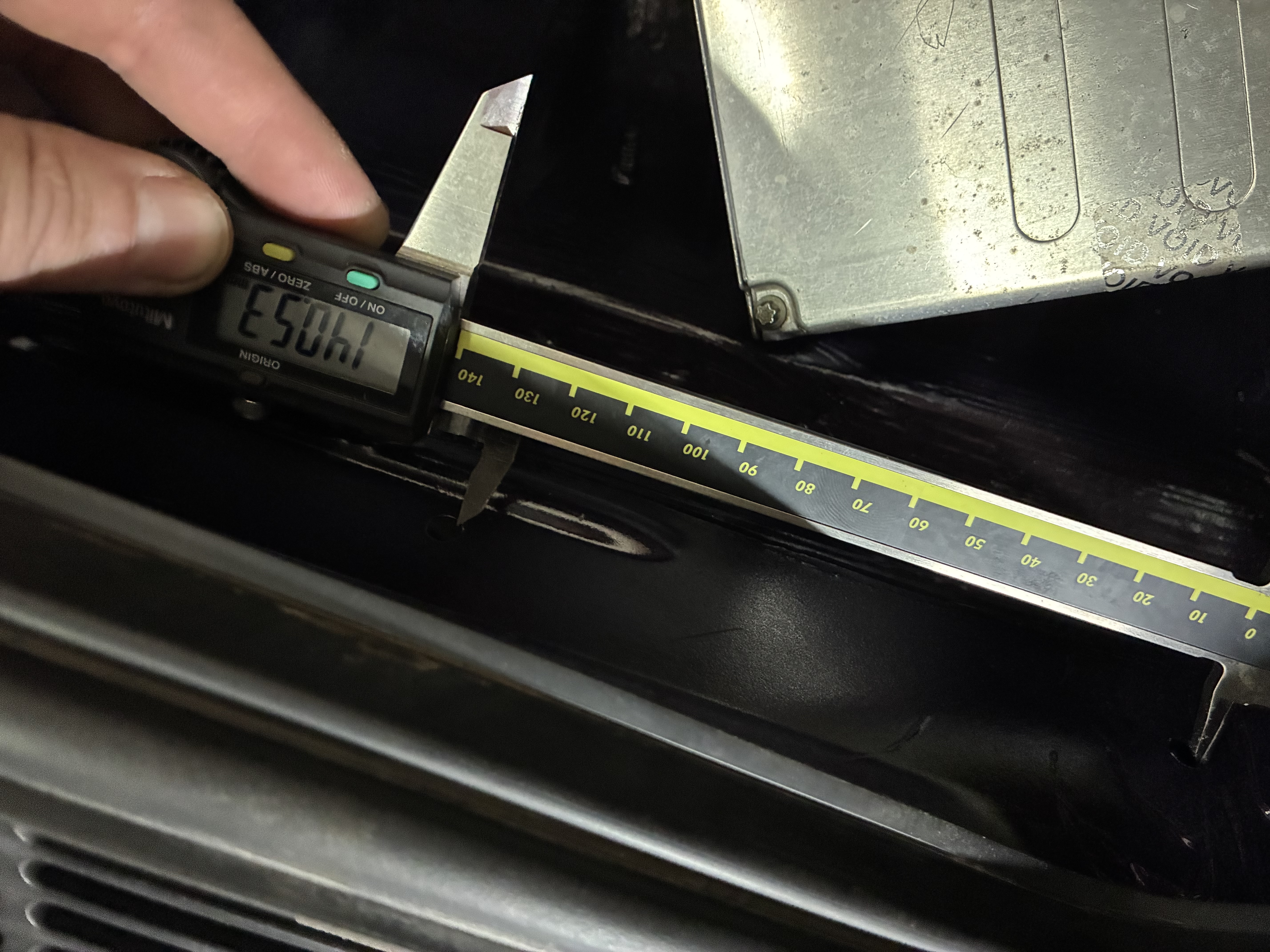
The resolution of the 3D scan is good, but not perfect. A combination of the virtual model for the general shape, and physical measurements for precise hole locations is used.
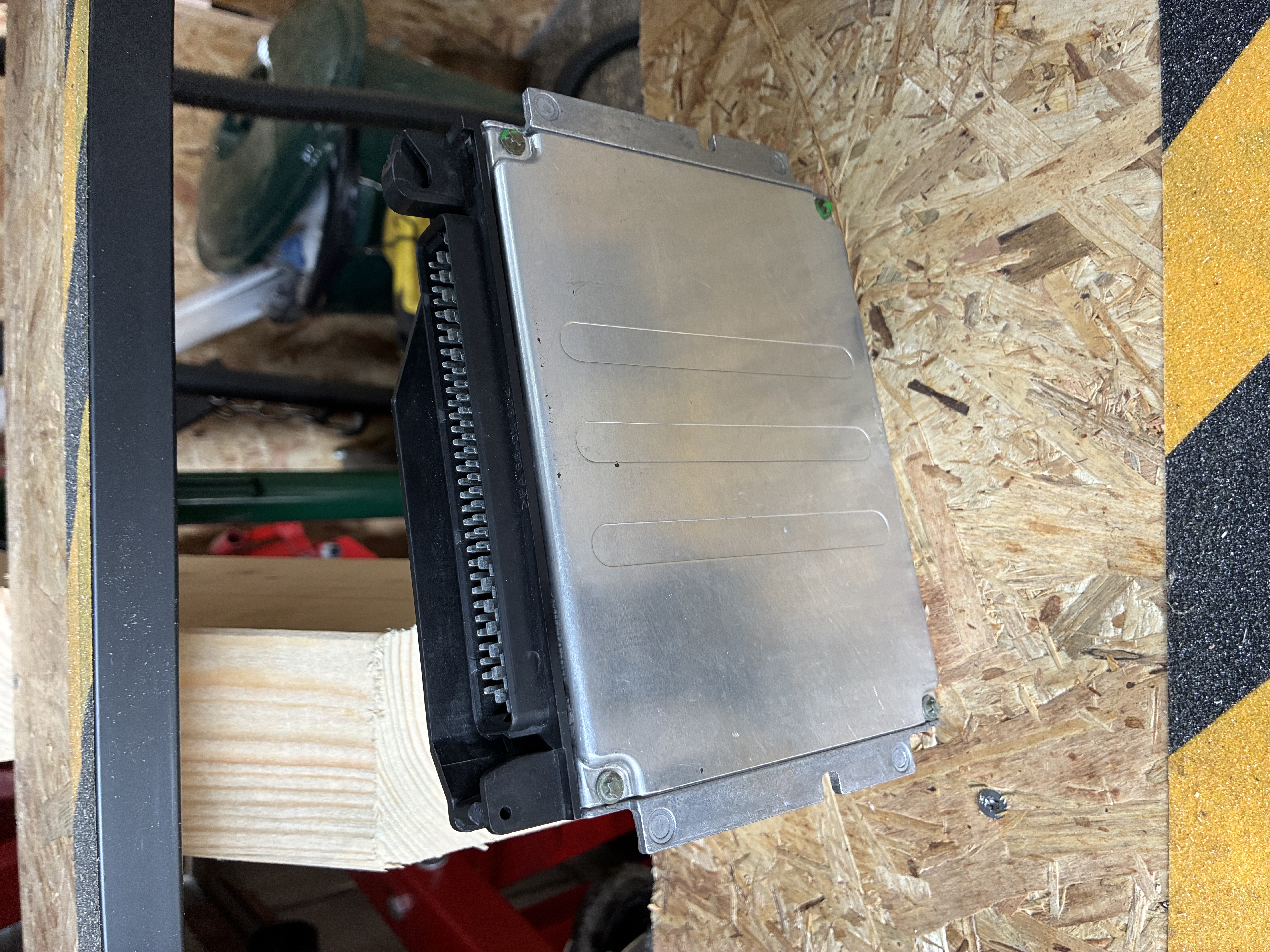
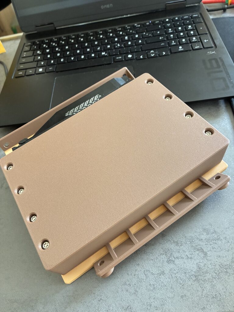
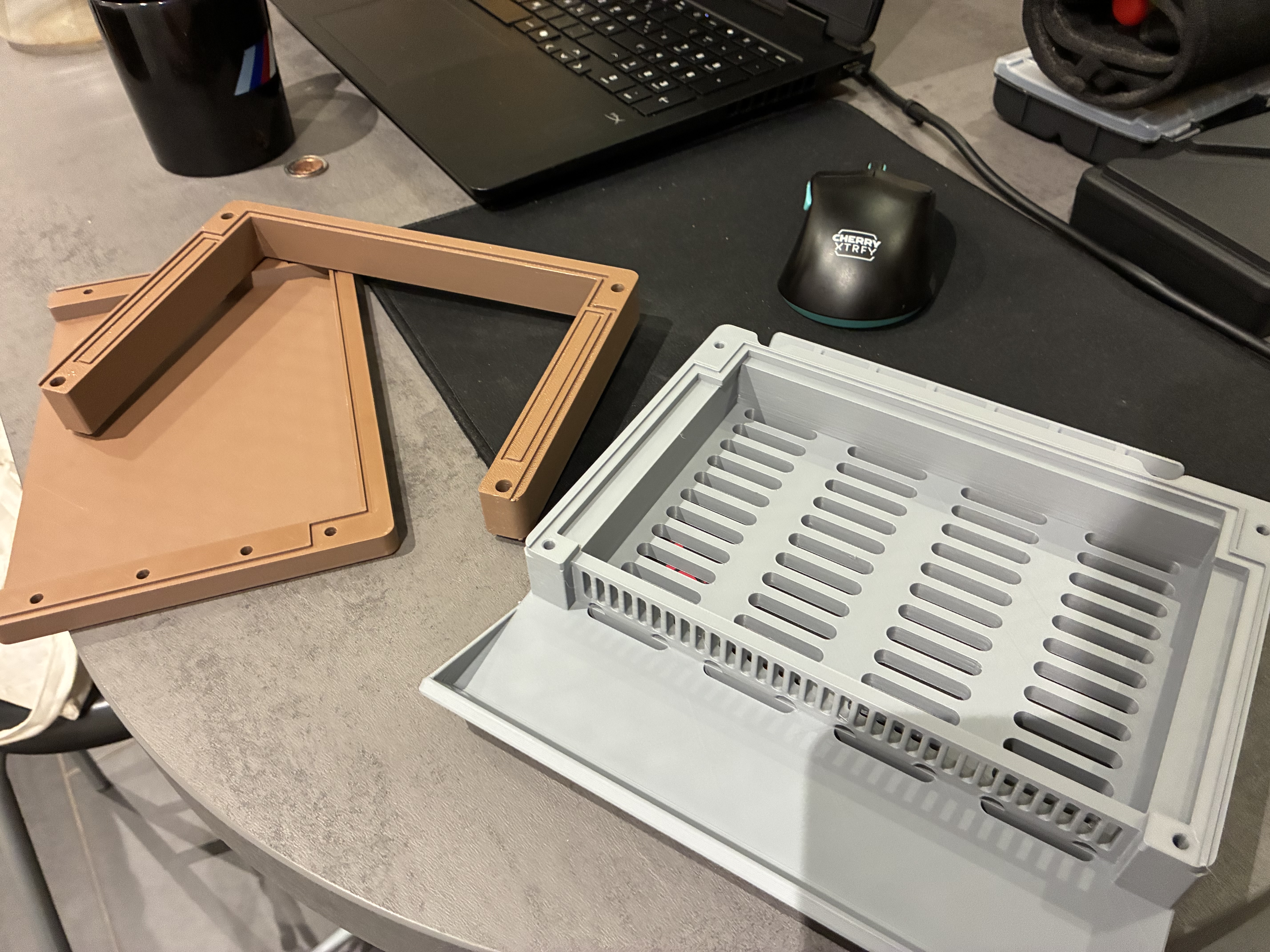
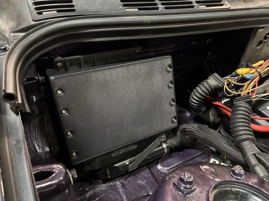
I designed a three part housing, consisting of a baseplate, spacer and lid, that holds the ECU with the connector facing downwards, allowing any stray water that might get to the pins to drain via gravity. The ECU is clamped in place by interfacing the original casting of the metal housing. Ventilation slots allow for cooling of the components inside.
At this point a first prototype can be printed using the cheapest and least desirable filament I found laying around.
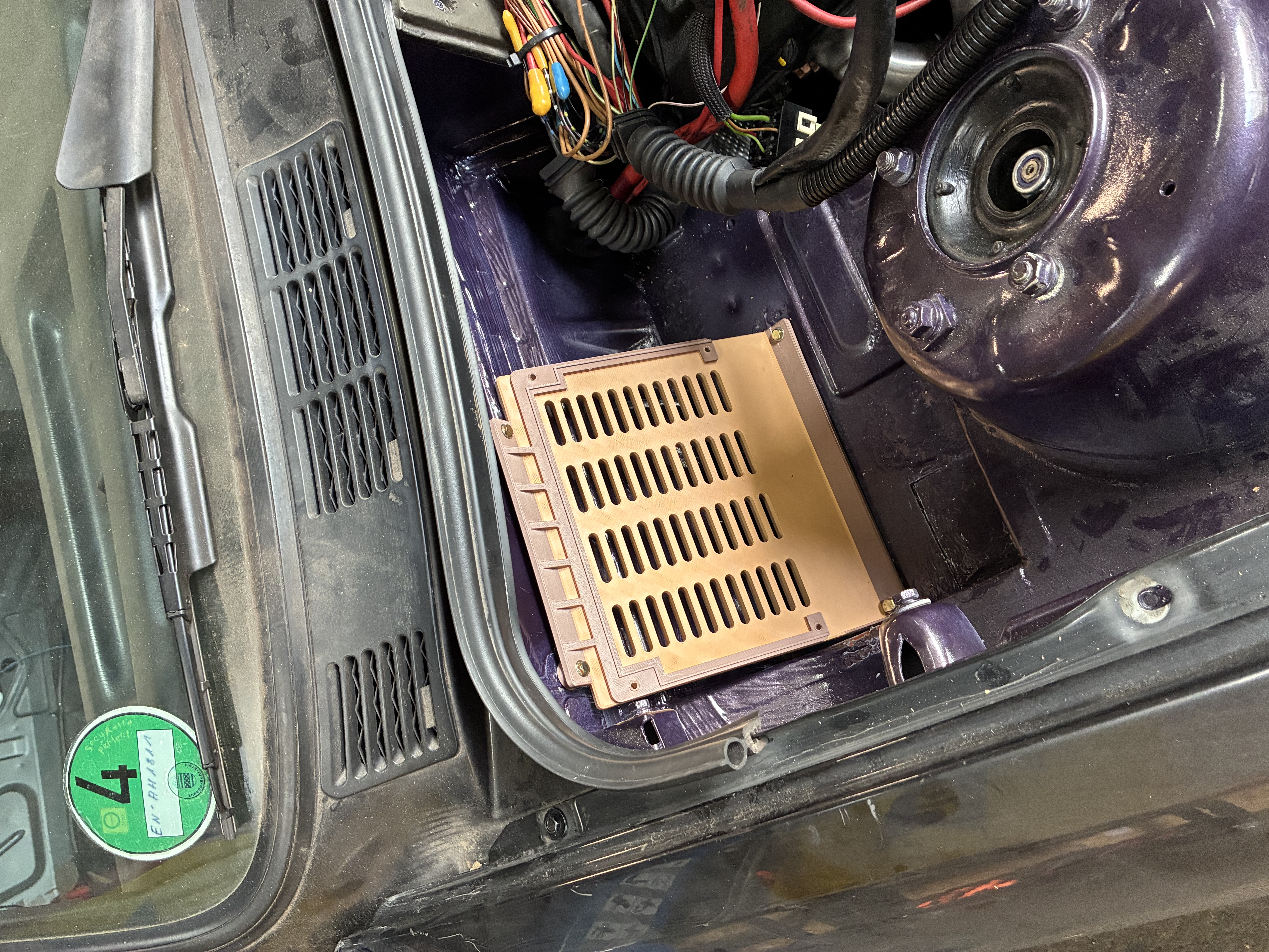
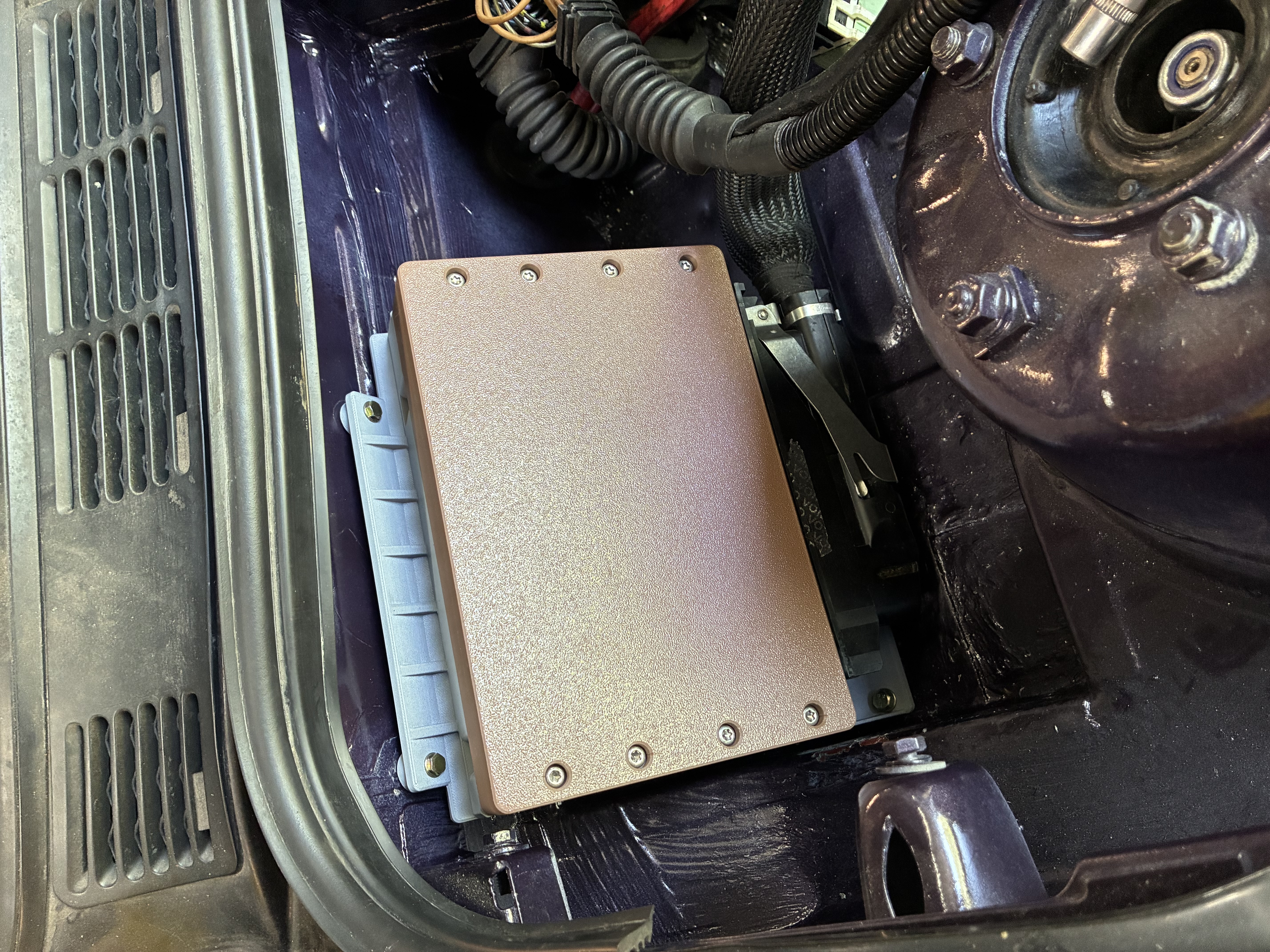
The prototype does not need be structural yet, it is only there to confirm hole locations, general fitment and any interference with other parts in the real world.
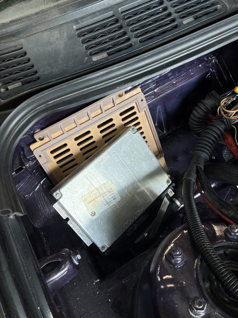
A couple of adjustments had to be made. Of course, the connector of the ECU was bigger than I assumed and did not fit, and the battery tray was not perfectly flat in reality. A second base plate was printed with the necessary changes. After checking again, we are ready to move on to the final part.
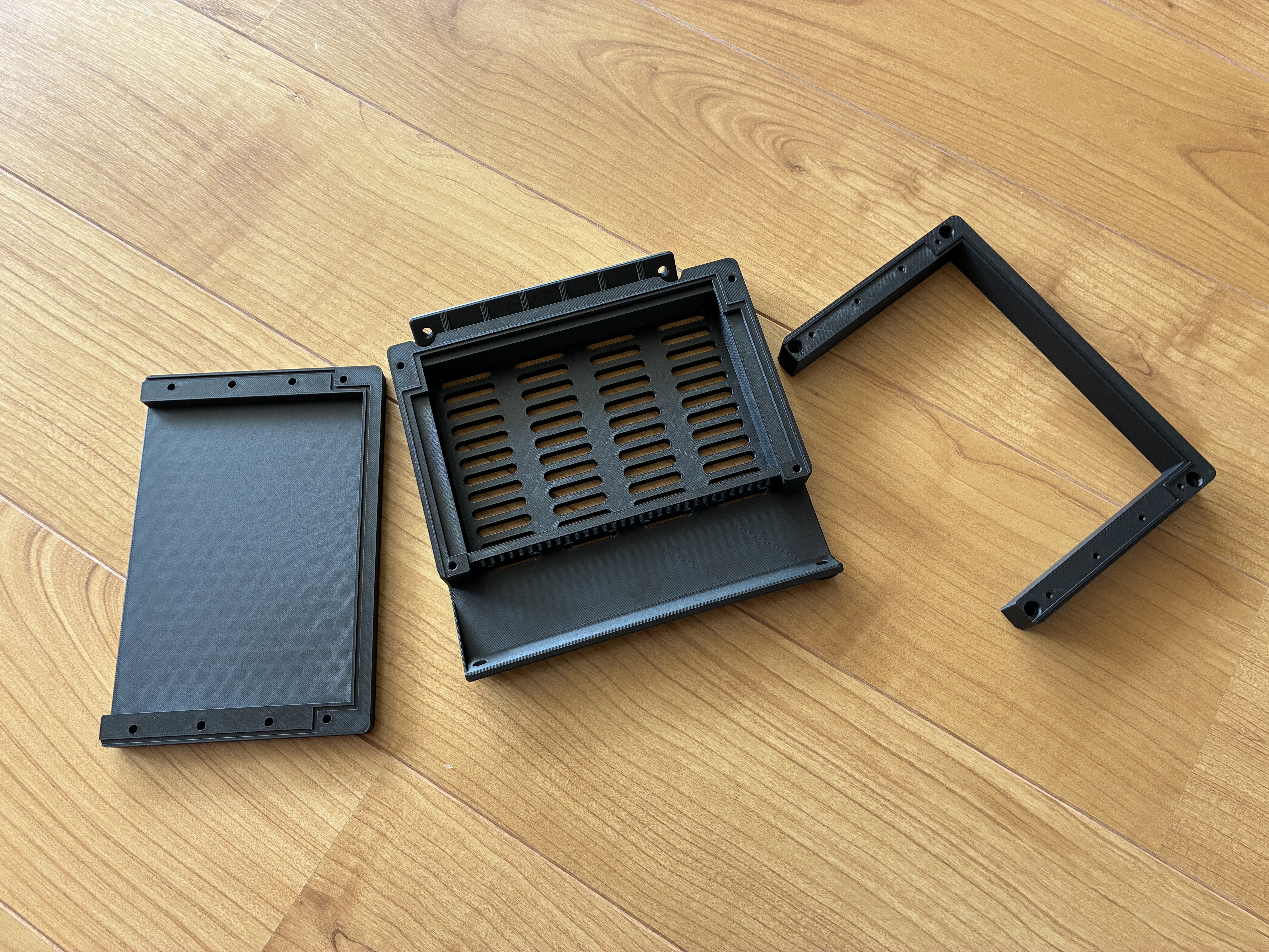
When making parts for automotive use, I like to use two materials in particular. ASA-CF and PPA-CF.
ASA is a cousin of ABS, which is the plastic used in most automotive applications. ABS is lightweight, relatively strong, moderately resistant to heat and chemicals and rather cheap. It is not however UV resistant or chemically stable over long periods of time, which anyone who has worked on old plastics in cars knows already. Over time it degrades and becomes extremely brittle.
ASA has many of the same advantages of ABS but is UV resistant and suitable for extended outdoor use, making it the superior choice for 3D printing most car parts.
The CF, meaning carbon fibre, just makes the part more dimensionally stable. Without embedded carbon fibres, most high temperature plastics are almost impossible to print without warping.
My other material of choice, PPA-CF, offers extreme resistance to chemicals like fuel, oil, brake cleaners, and temperatures above 200C. It is also exceedingly strong – an all around an amazing material, if it weren’t for the price tag of up to 200€ per kg. So printing in PPA is reserved for the most demanding applications, like the air box bolted right onto the engine (more on this in a separate post).
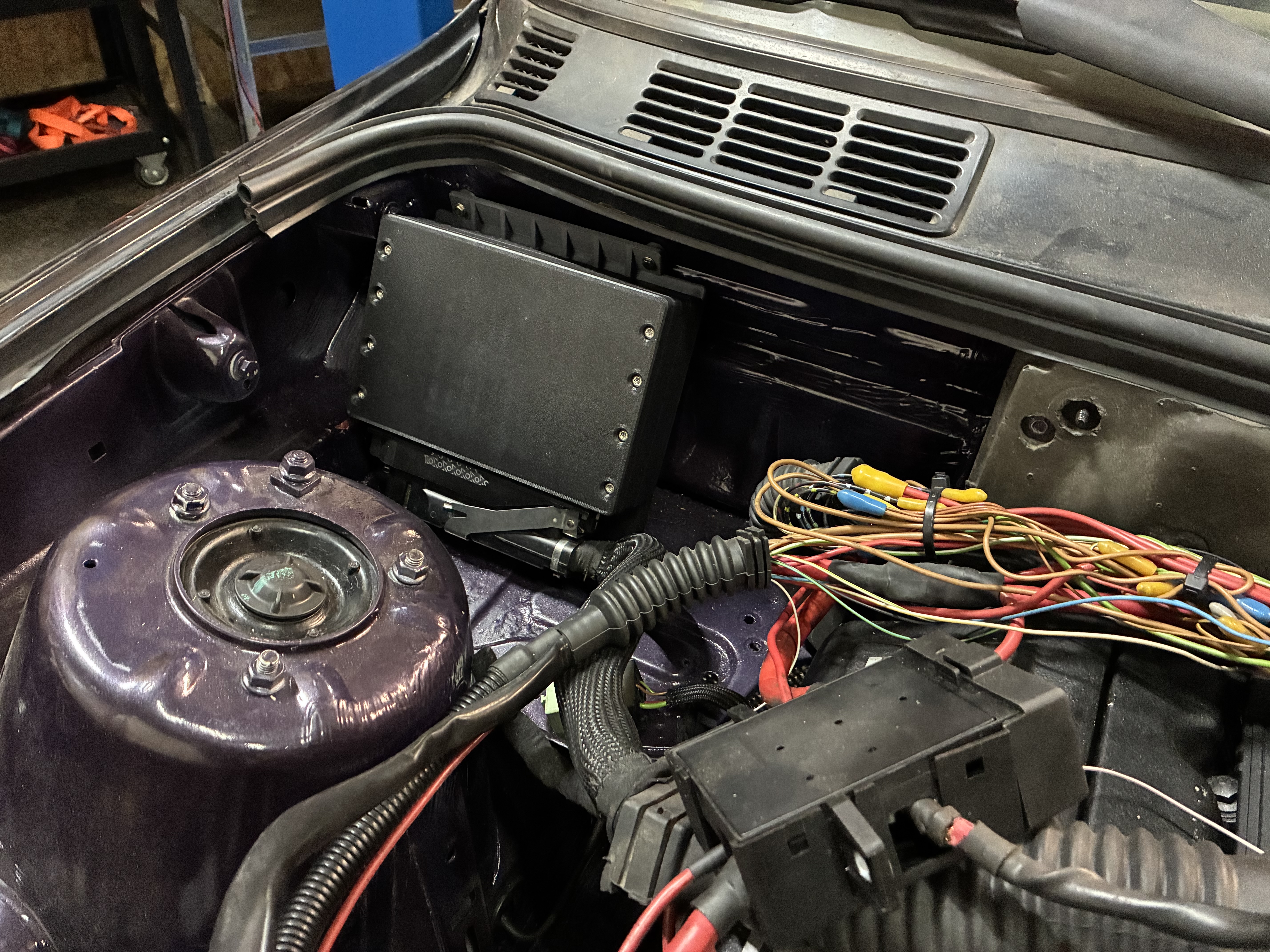
This is just one example of a custom part that would have been almost impossible to manufacture cost effectively at home in the past.
Other 3D prints in for this engine swap include holders for the power steering reservoir, battery positive terminal block and many more. With the advent of easy to use, click and forget 3D printing, projects like this are more accessible than ever before.
Leave a Reply